Random Projects
RGB LED Fun
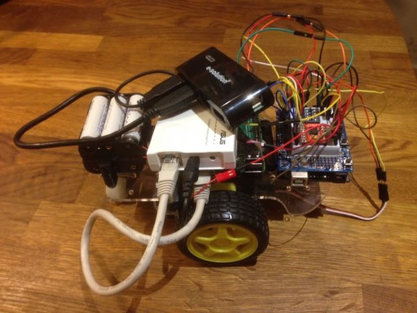
I recently bought some new toys: an Adafruit Feather M0 Express to play with Circuit/MicroPython and a Pimoroni Unicorn Hat to experiment with some ideas I’d had about visual notifications. I decided to put the two together in what started out as a simple test but quickly became a lesson in binary image files.
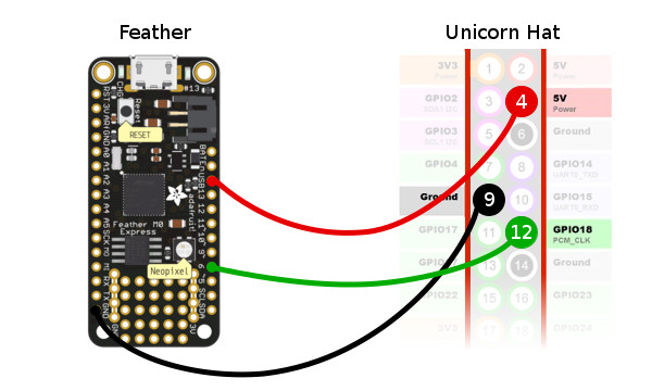
Connections
The Unicorn Hat uses WS2812 LEDs (aka. NeoPixels) so only requires three connections: signal, 5V and ground. These can be hooked-up via the GPIO connector or with a separate, unsoldered 3 pin header. Any digital pin on the Feather should work to provide the signal; I chose D6 for no particular reason. Here’s the circuit:
Code
With everything connected, making it do something is easy.
import board
import neopixel

pixels = neopixel.NeoPixel(board.D6, 64, brightness=0.025)
pixels.fill([255, 0, 0]) # Turns every LED red
Defining full-colour images in the code, however, is a very long and tedious task. The obvious alternative is encoding the desired image data in a BMP image but when I looked for a simple library to read BMP files in MicroPython, I came up short. As I’ve never worked directly with binary image files before, I decided to head down the rabbit hole and see what happens …
BMP File Format
The Wikipedia article on the BMP file format contains everything you’d need to know to write a simple reader. I started by creating a sample 8x8 pixel, 24-bit colour BMP file to match the specs of the Unicorn Hat. It looked like this, only much smaller:
Opening the file in a binary viewer reveals quite a simple format:
42 4D 3A 01 00 00 00 00 00 00 7A 00 00 00 6C 00
00 00 08 00 00 00 08 00 00 00 01 00 18 00 00 00
00 00 C0 00 00 00 13 0B 00 00 13 0B 00 00 00 00
00 00 00 00 00 00 42 47 52 73 00 00 00 00 00 00
00 00 00 00 00 00 00 00 00 00 00 00 00 00 00 00
00 00 00 00 00 00 00 00 00 00 00 00 00 00 00 00
00 00 00 00 00 00 00 00 00 00 02 00 00 00 00 00
00 00 00 00 00 00 00 00 00 00 7F 00 00 7F 7F 00
00 7F 00 00 7F 82 00 00 FF FF 00 FF FF 00 00 FF
FF 00 00 00 FF FF 00 FF FF 00 00 FF FF 00 00 FF
00 00 FF FF 00 00 7F 7F 00 7F 00 FF 00 00 FF FF
00 00 7F 7F 00 7F 7F 00 00 7F 7F 00 00 7F 00 00
7F 82 7F 00 00 7F 7F 00 00 7F 00 00 7F 82 00 00
FF FF 00 FF FF 00 00 FF FF 00 00 00 FF FF 00 FF
FF 00 00 FF FF 00 00 FF 00 00 FF FF 00 00 7F 7F
00 7F 00 FF 00 00 FF FF 00 00 7F 7F 00 7F 7F 00
00 7F 7F 00 00 7F 00 00 7F 82 7F 00 00 7F 7F 00
00 7F 00 00 7F 82 00 00 FF FF 00 FF FF 00 00 FF
FF 00 00 00 FF FF 00 FF FF 00 00 FF FF 00 00 FF
00 00 FF FF 00 00 7F 7F 00 7F
The interesting bits are the 14-byte file header, the first part of the image header and, of course, the actual image data. There’s more data encoded in the image header which we’d be interested in if we were writing a full parser but, as this is only intended for simple usage, we can be much more restrictive.
Reading BMP Files in Python
The first thing to remember when working with binary files in Python is to open them in binary mode.
with open('image.bmp', 'rb') as f:
    img_bytes = list(bytearray(f.read()))
Now that we have the individual bytes in an array, we need to do some binary manipulation to convert the multi-byte, little-endian numeric data into something more useful (eg: the 4-bytes representing the file size 0x3A 0x01 to integer 314).
def lebytes_to_int(bytes):
    n = 0x00
    while len(bytes) > 0:
        n <<= 8
        n |= bytes.pop()
    return int(n)
Now we can get data from the file and image headers:
filesize         = lebytes_to_int(img_bytes[2:4])   # 314
img_data_start   = lebytes_to_int(img_bytes[10:14]) # 122
img_data_length  = lebytes_to_int(img_bytes[34:38]) # 192
img_width        = lebytes_to_int(img_bytes[18:22]) # 8
img_height       = lebytes_to_int(img_bytes[22:26]) # 8
img_colour_depth = lebytes_to_int(img_bytes[28:30]) # 24
With the location and length of the image data, we can grab that too. Each byte represents either the R(ed), G(reen) or B(lue) value of a pixel.
pixel_data = img_bytes[img_data_start:img_data_start + img_data_length]
Pixel Sequence Manipulation
We have our raw pixel data from the BMP file with each pixel stored as 3 separate bytes representing the R, G and B values (or, being little-endian, B, G and R). The NeoPixel library can set a pixel’s colour with a [R, G, B] array so we should just be able to ‘pop’ the values off the pixel data array, right?
for i in range(64):
    r = pixel_data.pop()
    g = pixel_data.pop()
    b = pixel_data.pop()
    pixels[i] = (r, g, b)
Well, yes and no. This code will certainly cause the Unicorn Hat to display the image but the pixels will be a bit jumbled up because the BMP file stores pixels in a particular order and the Unicorn Hat arranges its LEDs in a completely different order, as this image shows:
![]()
By popping the image data from the array, we’ve inadvertently fixed the problem of it being upside-down but, because the image data is also stored left-to-right, we’ve reversed that too, so the LED rows which run left-to-right are reversed. To resolve this properly, we’re going to approach the problem in two stages. First, let’s shape the image data into a multi-dimensional array of rows and columns running left-to-right and top-to-bottom.
pixel_grid = []

for x in range(img_width):
    col = []
    for y in range(img_height):
        r = pixel_data.pop()
        g = pixel_data.pop()
        b = pixel_data.pop()
        col.append((r, g, b))
    col.reverse()
    pixel_grid.append(col)

top_left_px     = pixel_grid[0][0] # [255, 0, 0]
bottom_right_px = pixel_grid[8][8] # [0, 255, 255]
Now we can send the data to the Unicorn Hat, reversing the even-numbered rows so the image is displayed correctly.
i = 0
for row in range(img_height):
    for col in range(img_width):
        if row % 2 == 0: # Reverse the even rows
            col = img_width - 1 - col
        pixels[i] = pixel_grid[row][col]
        i += 1
Success!!
Library
All this code is great, but it’s not very reusable. I refactored the code developed above to create a library which can be included in any Circuit/MicroPython device by copying it to /lib. It’s available from my Github repository. Here’s an example of how to use it:
from bmp_reader import BMPReader

img = BMPReader('image.bmp')

img.width   # 8
img.height  # 8
px_grid = img.get_pixels()
Animation
If we can display one bitmap then we should be able to display several in sequence, creating a simple animation. One problem with the current code is that the image takes a while to display because we’re updating each LED as we set it. To solve that, we can unset the auto_write flag when we instantiate the NeoPixel library and only call the show() method once, when all the pixels are set.
pixels = neopixel.NeoPixel(board.D6, 64, brightness=0.025, auto_write=False)

[...]

pixels.show()
So now we can create an animation. With such a small device, the number of frames we can store in memory is limited. For a simple 6 frame animation, I needed to read the file each time I wanted to display it. It’s not optimal but it works and potentially allows for quite long animations. Here’s the code:
num_frames = 6

while True:
    for i in range(num_frames):
        pixel_grid = BMPReader('/frames/%s.bmp' % i).get_pixels()

        # Display the image as usual
        [...]
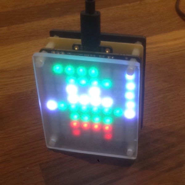
Here’s the 6 frame animation in action:
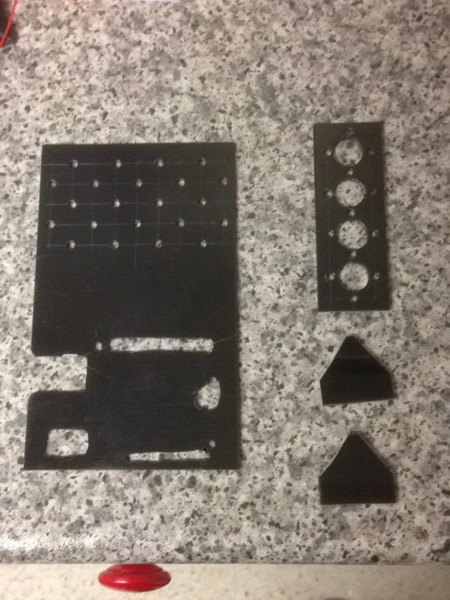
Case
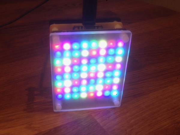
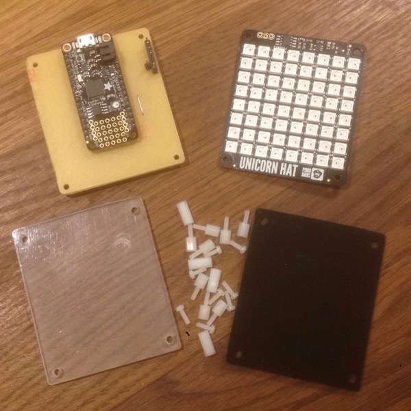
With everything working, I decided to build a little case for the whole unit to make it easier to stand on my desk. I hand cut a front panel from clear acrylic and a back panel from black acrylic using a fine-toothed wood saw, finishing the edges with a medium grit sandpaper. To diffuse the glare from the LEDs, I frosted the clear acrylic with sandpaper. My first attempt at a carrier board for the Feather using protoboard went wrong so I ended up etching something from single-sided copper-clad board instead. The whole lot was then joined together using nylon standoffs. The result is surprisingly elegant.
Conclusion
What started as a simple test of some new hardware has actually turned into quite a fun and educational project.
The Adafruit Feather board, with its ability to appear as a USB filesystem, makes the MicroPython development experience nicer, albeit more expensive than a basic NodeMCU device.
The diffusion on the front panel hasn’t worked as well as I’d like. Some frosted acrylic sheet or self-adhesive film might improve the result, as well as a 3D printed grid frame to isolate each LEDs light emission.
It’s also possible to buy 16x16 RGB LED devices :)
Resources
- Github: Simple BMP image library for CircuitPython
- CircuitPython docs: NeoPixel library
- Wikipedia: BMP file format
- Pimoroni: Adafruit Feather M0 Express
- Pimoroni Unicorn Hat
Posted on 15 December 2017