ROSbot
ROS Diff Drive Chassis Rebuild
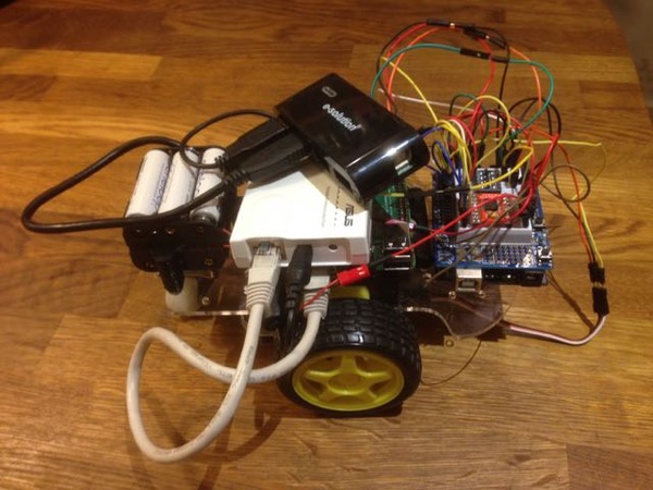
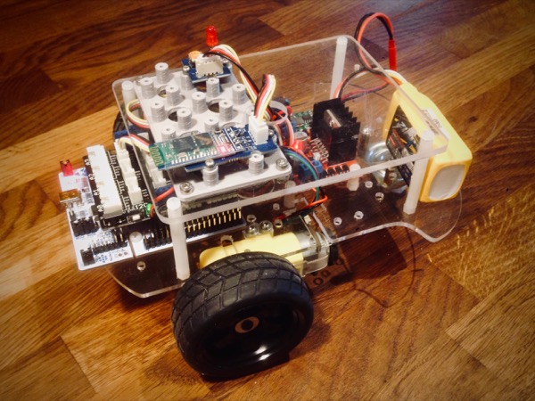
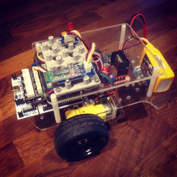
It’s time to bring this project back to life. When we last saw ROSbot, almost two years ago, it was moving under control of ROS but behaving strangely and the wheel encoders weren’t doing what they were intended to do. Since then, I’ve continued learning about ROS through reading and playing with the Gazebo simulator and I’ve recently been able to revisit this project with considerably more success. Here’s how things looked last time we saw ROSbot, and how it looks now:
A lot has changed so let’s dive in and take a closer look.
Chassis Layout
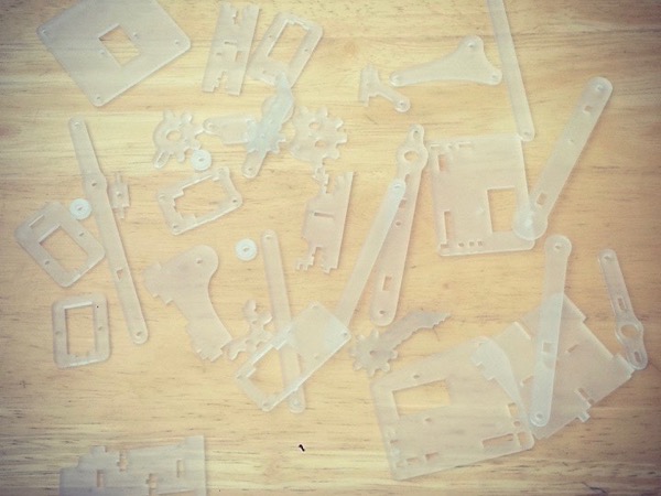
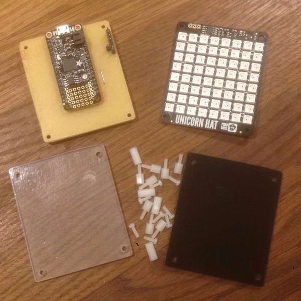
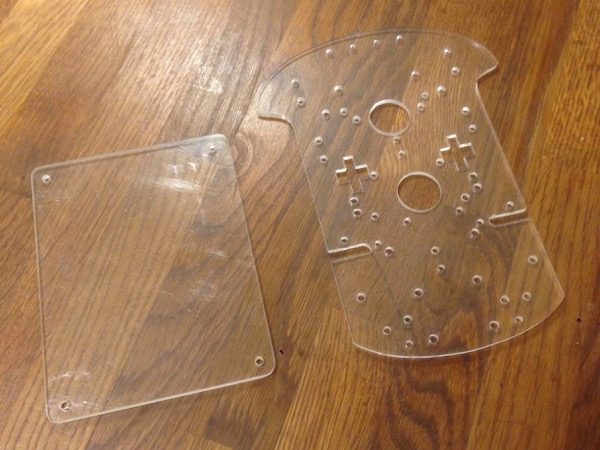
I had a major rethink of the component layout. The base controller board, motor driver and front sensors remain on top of the main chassis plate but I’ve made a new top plate, hand-cut from 4mm acrylic sheet, to hold the comms and other sensor/output modules. There’s also space for a Raspberry Pi at the front of the top plate for future use. I rearranged the wheels to improve stability as the robot was prone to tipping under sharp deceleration. The drive wheels are now at the back of the chassis and the caster has moved to the front leaving plenty of space in the middle for a good-sized battery. Here are the two plates:
Power
It was obvious that the 6xAA battery pack on the original configuration wasn’t going to be up to the job of powering the motors and various electronic components. In its place I’m temporarily using an 850mAH 3S LiPo battery (as seen in the photos) but this will be replaced by a 2200mAH 3S LiPo battery which should have plenty of capacity for the current configuration as well as for future expansion. The 12V of the 3-cell battery is stepped-down to 7.2V with an adjustable switching regulator ensuring, after the voltage drop of the motor driver regulator, that the motors get the 6V they need. The motor driver’s regulated 5V output supplies power to the base controller board.
Motors/Encoders
The ros_arduino_bridge base library uses PID to control motor speed and this, it transpires, depends on encoders with a much higher resolution than the 20 ticks/rev of the original motors. Once I figured this out and purchased new motors - conveniently with the same body but fitted with high resolution quadratic encoders - things started to look much more promising. I’m sure the original motors and encoders could be made to work with ROS but it would mean not using this library with its closed-loop wheel speed sensing and other features, which I don’t want to do.
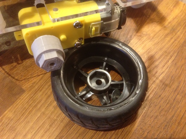
Annoyingly, although the new motors use the same body parts and look almost identical, they have a metal drive shaft which has an ever-so-slightly smaller diameter, meaning the original wheels don’t fit. I ended up designing and printing an adaptor for a standard 12mm RC car hex adaptor to go with some shiny new wheels.
Base Controller Board
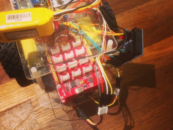
After some experimenting, I finally came to the conclusion that the high resolution of the new encoders was causing problems. I was able to get one side’s motor/encoder working reliably but not both sides at the same time. This pointed to the 8-bit Uno board not being able to process the interrupts fast enough in addition to its other responsibilities so I decided to try running the code on a faster STM32-based board I had lying around. Here it is, literally hanging off the chassis for testing:
The on-board encoder driver code in the base library is specifically designed for Uno boards so I needed to write a new one for the 32-bit board. The easiest (but certainly not most efficient) way to do this was to use the attachInterrupt function and adapt some generic quadrature encoder-reading code from the Arduino Playground. Here are the essential bits for reading the left-side encoder0 (duplicated variables and functions for encoder1 have been removed for brevity):
volatile unsigned int encoder0Pos = 0;

boolean A0_set;
boolean B0_set;

// Interrupt on 0A changing state
void doEncoder0A() {
    A0_set = (digitalRead(encoder0PinA) == HIGH);

    if (A0_set && !B0_set) {
        encoder0Pos = encoder0Pos - 1;
    }
}

// Interrupt on 0B changing state
void doEncoder0B() {
    B0_set = (digitalRead(encoder0PinB) == HIGH);

    if (B0_set && !A0_set) {
        encoder0Pos = encoder0Pos + 1;
    }
}

void initEncoders() {
    pinMode(encoder0PinA, INPUT);
    pinMode(encoder0PinB, INPUT);
    [...]

    attachInterrupt(encoder0PinA, doEncoder0A, CHANGE);
    attachInterrupt(encoder0PinB, doEncoder0B, CHANGE);
    [...]
}
The test was successful so I purchased a new STMicro Nucleo F103RB board with Arduino-compatible headers, hooked everything up more permanently and topped it off with a Grove Arduino shield (I’m having a bit of a Grove love-in at the moment). The 32-bit board brings a number of advantages beyond faster processing: it has interrupts on every pin (avoiding one of the biggest shortcomings of the 8-bit Arduino boards) and a large number of GPIO pins beyond the regular Arduino offerings, meaning I can assign motor driver duties to non-Arduino pins. This will leave more room for connecting sensors on the Grove shield.
Motor Driver
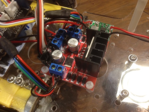
To exclude one potential source of bugs while diagnosing my original motor issues, I replaced the TB6612FNG driver with a cheap L298 module which is already supported in the base library. This didn’t make any difference but I ended up sticking with it anyway as it allowed me to fit the Grove shield without needing to increase the space between the two body plates.
One minor disadvantage of the new 32-bit base controller board is that it has fewer PWM pins. The L298 driver code uses PWM on both the forward and reverse pins of each motor meaning a total of four PWM pins. It’s possible to halve this number by applying the PWM signal to the motor enable pin and setting the direction using regular digital pins so I updated the code to do this. Here are the major changes:
void setMotorSpeed(int i, int spd) {
    int fwdPin = LEFT_MOTOR_FORWARD;
    int backPin = LEFT_MOTOR_BACKWARD;
    int enPin = LEFT_MOTOR_ENABLE;

    if (i == RIGHT) {
      fwdPin = RIGHT_MOTOR_FORWARD;
      backPin = RIGHT_MOTOR_BACKWARD;
      enPin = RIGHT_MOTOR_ENABLE;
    }

    if (spd < 0) { // Backwards
      digitalWrite(fwdPin, LOW);
      digitalWrite(backPin, HIGH);
    } else if (spd > 0) { // Forwards
      digitalWrite(fwdPin, HIGH);
      digitalWrite(backPin, LOW);
    } else { // Stop
      digitalWrite(fwdPin, LOW);
      digitalWrite(backPin, LOW);
    }

    analogWrite(enPin, abs(spd));
}
ROS System and Communications
My original plan was to run ROS on a Raspberry Pi mounted to the chassis. I may eventually return to that plan but, to make development easier, I’m currently running ROS in an Ubuntu VM on my laptop and communicating with the base controller via Bluetooth. This seems to work well and allows me to take advantage of the much greater processing power of my laptop as well as providing a more convenient development workflow with direct access to the ROS code on my main system.
A useful note for getting Serial-over-Bluetooth running in Ubuntu which might prove useful to other people (I went down a few wrong paths before I eventually found this solution):
me@ubuntu:~$ sudo hcitool scan
Scanning ...
{hex_device_addr} device_name 000000
me@ubuntu:~$ sudo rfcomm bind /dev/rfcomm{number} {hex_device_addr} 1
Yes, it really is that simple - just replace the contents of the curly braces with appropriate values. No need to install Blueman or any of the other stuff you might read elsewhere on the Internet.
Conclusion
It’s taken some time to get here but it’s very satisfying to have worked through all of these problems and finally have a working robot base. In hindsight, what’s going on in the robot base code isn’t overly complicated and a lot of the trouble I’ve had has been because of my lack of understanding - first of the interactions within ROS itself and, more recently, of the limits of the 8-bit Arduino platform. Reading got me over the former and switching to a 32-bit board, the latter. I have no doubt it’s possible to get something working with an 8-bit board, much as I’m sure it’s possible to use the original low-resolution wheel encoders with ROS but I’m going to stick with what’s working so I can learn more about the advanced control and navigation features in ROS.
I can now get on with attaching sensors and exploring ROS in more depth so expect more post on this project soon. Here’s a photo of the finished base:
Resources
- Github: ROS Arduino Bridge (my fork)
- Arduino Playground: Rotary Encoder Example
- STMicro: Nucleo User Documentation
- Thingiverse: ROSbot Parts collection
Posted on 02 December 2017