Badminton Scoreboard
Handsets
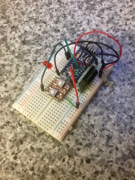
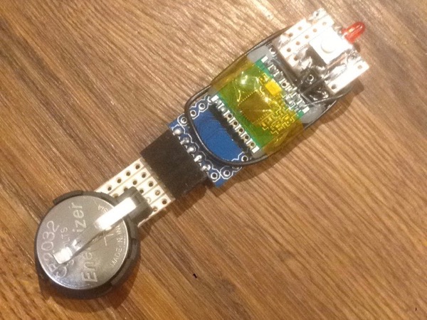
Hot on the heels of the main unit prototype, here are the handsets. Aside from the obvious encasement, the main changes from the original prototype are that I’ve powered them from a 2032 lithium cell and that the team/colour is now set with a hardware jumper rather than in code. Here are a couple of photos showing the original prototype and the finished item:
Team Selection
In the original version, the team for each handset was set as a constant in the code:
#define MYNODEID 1

void setup() {
    radio.initialize(FREQUENCY, MYNODEID, NETWORKID);
This meant that each handset’s firmware needed to be modified and compiled individually, which isn’t ideal. To avoid this in the final units I defined a digital pin as team selector, connected this pin on one of the handsets to ground and then detected the state in the code at runtime to set the team:
void setup() {
    int myNodeId = 1;
    pinMode(NODE_PIN, INPUT_PULLUP);

    if (digitalRead(NODE_PIN) == LOW) {
        myNodeId = 2;
    }

    radio.initialize(FREQUENCY, myNodeId, NETWORKID);
Power
I had some trouble deciding between a non-rechargeable 2032 lithium “coin” cell and a small, rechargeable li-ion cell. The advantage of the latter is the ability to recharge the units but I was concerned that the additional charging and regulation circuitry would make the handsets too bulky. Conversely, while coin cells would be more compact and safe to connect directly to the RFM modules, they could be far more expensive in the long-term if they discharge too quickly in use.
There’s some good information about running Arduinos for long periods on coin cells so I decided to start with this option but to make the power supply a separate module so I could change my mind if it didn’t work out after a few months of use.
The 3.3V/8MHz Arduino Pro Mini is an ideal off-the-shelf starting point for a low-power device like this but it does need a few modifications to make it really efficient. I won’t repeat those modifications here but links are in the References section, below, for anyone who’s interested.
For the code I used the LowPower library to put the handset into permanent sleep, waking only when the button is pressed:
#include <LowPower.h>

void loop() {
    // Allow wake up pin to trigger interrupt on low.
    attachInterrupt(1, wakeUp, LOW);

    // Enter power down state with ADC and BOD module disabled.
    // Wake up when wake up pin is low.
    radio.sleep();
    LowPower.powerDown(SLEEP_FOREVER, ADC_OFF, BOD_OFF);

    // Disable external pin interrupt on wake up pin.
    detachInterrupt(1);

    [...]

    // Sleep for 8 seconds
    LowPower.powerDown(SLEEP_4S, ADC_OFF, BOD_OFF);
}
The extra sleep at the end of the loop ensures a suitable delay between detecting a button press and listening for the next one. In my first real-world test, I forgot to put the radio to sleep and the battery was drained by the following week. The addition of the radio.sleep() call seems to have solved the problem with the handsets running on the same batteries for 5 weeks and counting at the time of writing. I have subsequently added a 10uF electrolytic capacitor to avoid problems with the radio drawing with too much current on waking.
Electronics
The circuit is very simple - just an Arduino, the battery, radio module, an LED and a tactile switch. On a side note: this was the last time I used my old soldering iron - the tip was so large and the work so fiddly that it was like doing brain surgery while wearing boxing gloves.
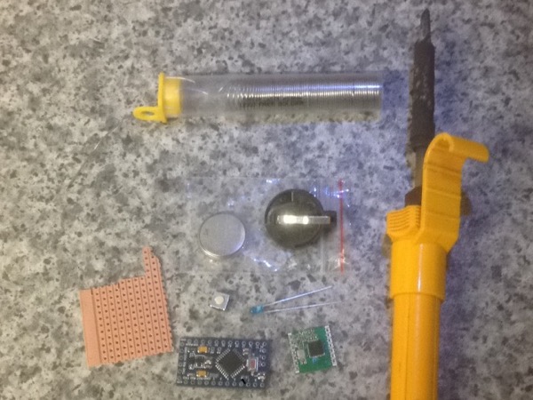
There’s a small piece of stripboard securely soldered to one end of the Pro Mini which holds the LED and switch. The radio module is connected with single-core equipment wire and secured in place with hot glue. The antenna is then wrapped around the whole unit and held in place with kapton tape. It looks a bit messy but the end result is solid:
Case
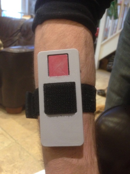
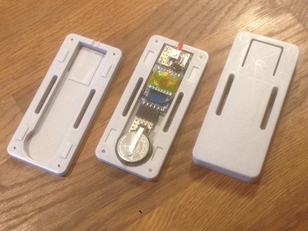
I designed a small 3D-printed case. It features a flexible cutout area over the tactile switch on the board, a cutout for the Arduino’s reset button on the back and slots for an elasticated armband which I purchased from Amazon. It’s printed in two halves, has some tapered blocks to ensure good alignment and is secured with small self-tapping screws. Here’s a photo of both halves alongside an assembled unit:
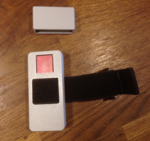
The button is easy to press accidentally when being transported and stored - something I noticed when the battery ran out overnight before our first game - so I also designed and printed a cap to prevent this. Here’s the handset with the cap, coloured (with permanent marker) button and armband.
Conclusion
I hadn’t worked with Arduino’s low-power functions before so this was an educational experience for me. The end result is very satisfying and I don’t think I’d do much differently if I were to do it again - only time will tell if using coin cells was the right choice, of course. My biggest concern is that the finished units are a bit larger than I’d like so, for a future revision, I may have to consider designing a custom PCB.
Resources
- Low power Pro Mini: MySensors.org
- Handset code: Github
- Main case model: OnShape
- Case cap model: OnShape
- Gymboss wristband: Amazon
Posted on 04 February 2018