Mostly Printed CNC
Wiring, Spindle and First Test
With a clear weekend ahead of me, it was time to finish this project. First up was wiring the stepper motors. With the exception of briefly forgetting how internal stepper wiring works, everything went smoothly. I made a simple extension board to allow me to connect the two motors on each of the X and Y axes to the single connection point on the CNC shield, remembering to reverse one of the coils in each pair so both motors go in the same direction. To stop the Z axis cables from dragging in the moving parts, I used a length of electrical trunking fixed across the top of the Y axis middle rail:

The 400W spindle motor arrived and dropped straight into the printed holders:

I had some old 17A automotive cable lying around which, while quite rigid, was the only option available to me for connecting the motor if I wanted to finish assembly this weekend.
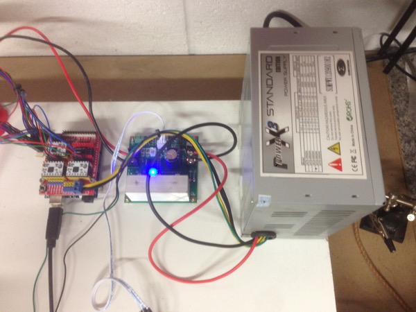
As for the power supply, I decided to repurpose the 500W PSU from my old Prusa i2. I needed to pop the cover off and solder some of the unused ground and 12V wires to a couple of short lengths of the 17A cable to power the spindle driver board. Here’s a photo of the PSU and control boards in place:
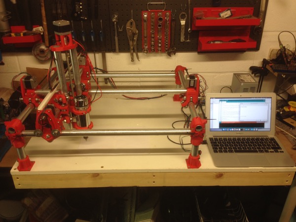
With everything connected, I powered it up and connected my laptop to do some testing and configuration. Here’s a photo of that in progress (now you can see why I left a space at the side of the base):
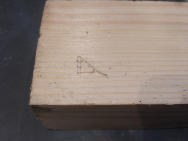
Maximum working area is 380mm x 310mm. I don’t have a proper milling bit at the moment but I used a small grinding bit from my multitool and some scrap pine to do my first test cut. The pine was hot-glued to the board … which turned out to be a bad plan - the glue was so strong it pulled the lamitate off the chipboard. Grrr!
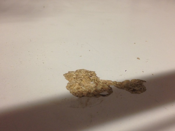
Here’s a photo of the first cut, showing a 10mm sided triangle. It’s not a lot but “from small acorns” and all that …:
Initial Thoughts/Observations
The Y axis moves a little jerkily, which I was concerned about during the build because it felt a little tight. I’m hoping it’ll settle in a bit but if it doesn’t or if it causes problems with cutting, I’ll have to do something about it. The Z axis has a similar problem but I think I can fix that with a different motor coupler - the current one has a sprung section to allow for poor alignment but that’s allowing the slightly sticky movement to be passed on to the axis movement.
I’m going to need to spend some more time on cable management. Cable chains would be a worthwhile upgrade, especially for the motor and Z axis cables which sit on top of the Y rail, and I also want to add some grommets and strain-relief to prevent damage where the stepper motor wires enter the middle rails. I may also switch from the rigid 17A automotive cable to some more flexible silicon cables.
The motor driver board is currently being controlled manually by a potentiometer but it has a connection for Mach 3 PWM control so I’ll investigate whether that will work with GRBL’s motor speed control output so it can be controlled in software.
But before any of that, the next step is to order some proper milling bits, decide on a better way to attach the waste board and find some suitable toolpath generation and controller software. Then I can get on with some real cutting and see how it performs in actual use.
Posted on 31 July 2016