Reprap Prusa i2
First successful print dry-run (with video!)
The title says it all. I finally got it working at the end of the day after a long fight with the electronics. There’s still some work to do as it’s not working perfectly yet, but it’s good enough to move onto wiring the hot-end components next week. Here’s a video of the dry-run, followed by a run-down of the day’s activities:
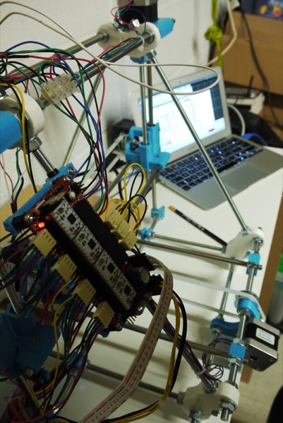
I started by fixing the axis issue from yesterday. I made the relevant changes to the Sprinter settings and re-uploaded the firmware. Simple, and it worked. Well, almost. The next step was to do a full test of the motors and stops. The Y and Z axes worked fine but the X axis only moved in one direction, regardless of which way I told it to move. I checked the voltage on the direction pin for each of the Pololus and, sure enough, they all behaved properly (switch between 0v and 5v depending on the direction) except the X axis which stayed at 5v. My first thought was that it might be a short on the board due to my cludgy soldering so I did a thorough check on all the pins but everything seemed in order. Next thought was that the Atmel might have developed a fault after all my messing about yesterday so I programmed up the spare and tried that. Same behaviour. Curious. Heading back to Google, I eventually found a forum thread suggesting that the problem might be caused by the default value for the JTAG fuse forcing that pin high. It’s been a long time since I did anything with microprocessor fuses so it took me a while, not helped by the fact that I had to recommission my makeshift Arduino programmer from yesterday. I eventually got the fuses changed and tried the board. It worked! As this fuse is the default in an Atmel 644P and the Sanguinololu 1.3 board isn’t exactly cutting edge, I’m surprised it isn’t a more widely documented issue.
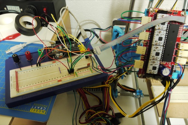
The next step was to configure the axis directions in the firmware as they weren’t matching up with the controls or stop positions. This should be a simple task by now but, of course, it wasn’t. Apparently, changing the fuses broke USB programming :( I’m still not sure what was causing this problem and the ensuing “set fuses, burn bootloader, upload firmware, test, repeat” cycle got really frustrating. There were several occasions where I was tempted to put it all away for the day. I eventually decided to stop for lunch and take stock of things. It was then that I remembered a new feature I’d noticed yesterday in the Arduino IDE menus: “upload with programmer”. I wasn’t sure if this would work but I tried it and, thankfully, it did. So, I can now control the board with the FTDI breakout board and I can burn the bootloader and upload new firmware with my Arduino programmer. Not ideal, but at least I’ll be able to move forwards now. Here’s a photo of the programmer in all its Heath Robinson-eque glory. Note how it balances precariously on the edge of the shelf in order to reach the board :D
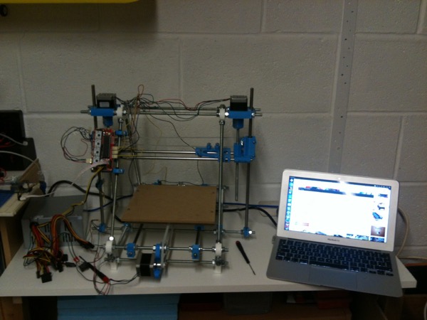
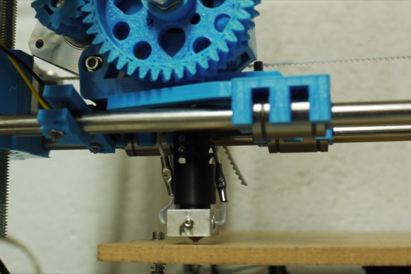
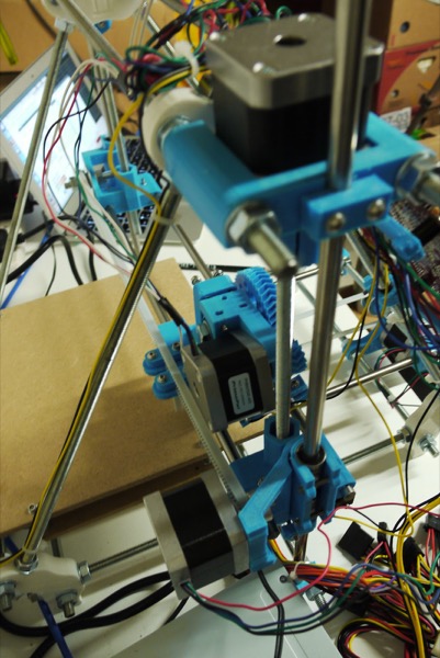
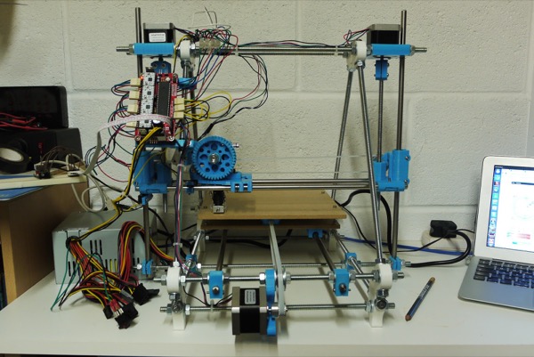
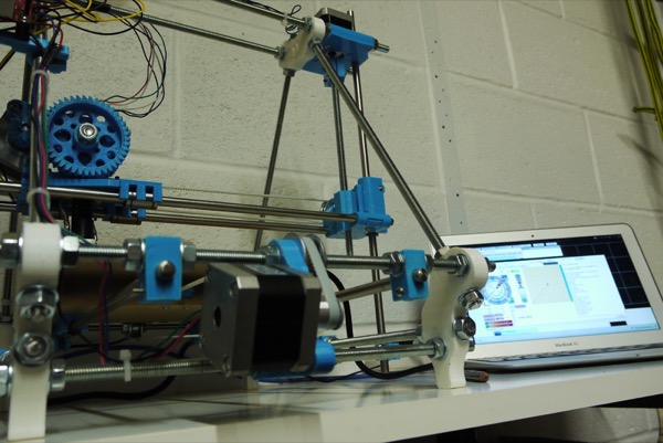
After all of that, the rest of the day went smoothly. I bolted the Z-motors down (including more plastic part tidying) and re-fitted the Z-axis couplings to reduce the wobble I’d noticed during testing. Then I wrapped the hot-end heating resistor in aluminium foil, fitted the extruder to the X-carriage and finished routing the wires neatly around the frame. Finally, I checked and configured the print dimensions in the firmware. And then came the big moment: the first print dry-run. I picked a small item from Thingiverse, loaded it and hit the ‘print’ button. After a frustrating weekend, it was really rewarding to watch the hot-end moving around. There’s still work to be done next week: getting the hot-end working, insulating hot components with the Kapton tape I ordered yesterday and taping up the print bed with blue masking tape; but I expect to be ready for my first real print next weekend at the latest.
I’ll leave you with a few more photos:
Posted on 04 November 2012