Reprap Prusa i2
PCB fitted; end stops and belts loosely fitted
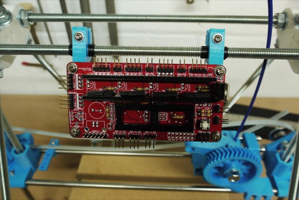
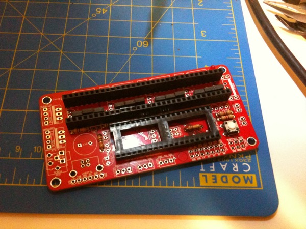
A few updates this evening. I finished soldering the electronic components I had in stock and ordered the remaining items from Farnell which should be here in a couple of days (except the Atmel which is waiting on a delivery from their supplier). The board holders have been fitted to the top frame which you can see in the photo, above, so I can start wiring up at some point.
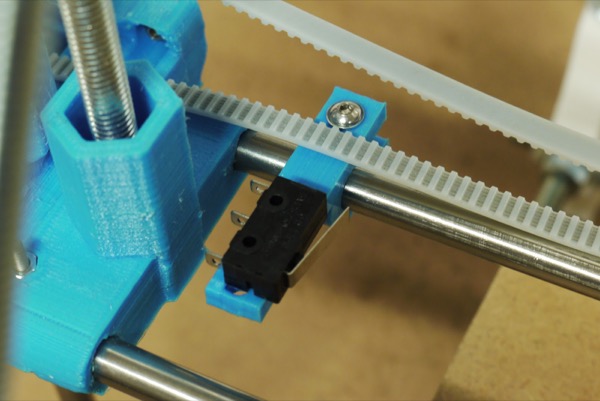
The morning’s post brought a length of timing belt and two aluminium pulleys (all the way from Denmark!) and the microswitches for the end stops. I had to drill new holes on the end stop holders as the switches’ holes are smaller and closer together than the holders were designed for. I don’t want to glue them as it’ll make them less reusable so I’ve ordered a small number of M2 screws, nuts and washers. All three end stop holders are fitted in the recommended locations and I’ve rested the microswitches in place temporarily to ensure they make contact with the intended parts. You can see the X and Y stops in the two photos, below.
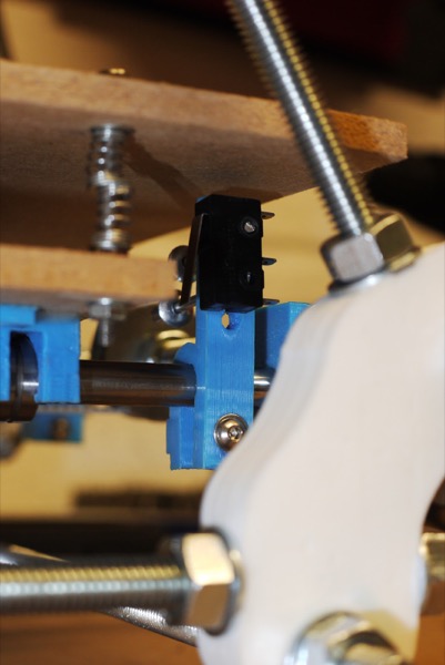
The belts have been cut roughly to length, allowing for the motors to be fitted when they arrive. With the belt in place on the Y-axis it became obvious that what I’d assumed were a couple of redundant plastic parts are actually part of a non-standard belt clamp design. As with the rest of the plastic parts, they needed the captive nut inserts cleaning up. I then fitted everything properly and tensioned the belt (without the motor) to see how it runs.
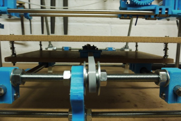
I’m a little concerned that the belt is going to bind too easily on the bearing washers based on initial tests. This is one of the reasons the official Prusa v2 parts include contoured covers for the 608 bearings rather than using the button washers from earlier versions. I didn’t receive these covers in my plastic parts so, if belt binding proves to be a problem once everything’s running, I’ll have to decide how to resolve it. A few options are to print my own (assuming the printer’s producing parts of a suitable quality by then), find someone willing to print them for me or use stuff I already have to guide the belt to the bearing more accurately. To wrap up this post, here’s a photo showing the tensioned Y-axis belt and clamp.
Posted on 30 October 2012