Reprap Prusa i2
Building my first RepRap
I wish I’d thought to keep a build log from the very beginning of this project. Still, it’s only been a few weeks and just a few hours of actual build time. Here’s a summary of what’s happened so far.
I’m building a RepRap Prusa 3D printer with the aim of doing it as cheaply as reasonably possible without incurring significant delays by making any particularly problematic parts. That means I’m shopping around for the best prices on hardware and will be assembling the electronics myself rather than buying a kit but I’ll be buying printed plastic parts, a pre-etched PCB and an off-the-shelf extruder hot-end for this first build. Target price is around £250 and I’m hoping to print my first piece before Christmas (2012).
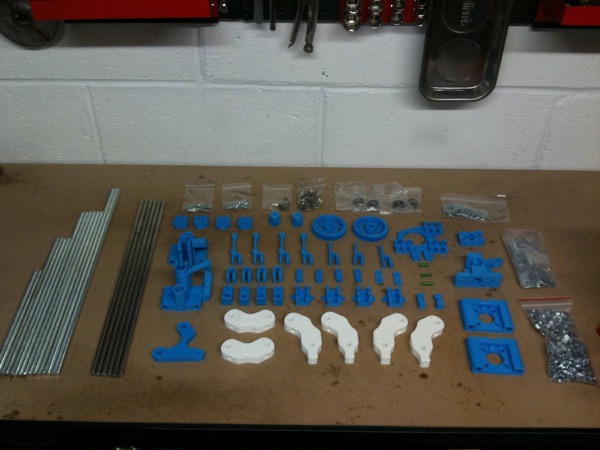
The photo above shows pretty much everything needed for the first stage which is to build the frame, axes and extruder body. Missing are the linear bearings, extra skateboard bearings for the extruder, a hobbed bolt, some odd sized nuts/bolts and springs which were all on order; the linear bearings and hobbed bolt are the only outstanding items at the time of writing.
The threaded bar and stainless smooth rods were cut to the specified sizes with an angle grinder in a stand and smoothed with a metal-sanding disc. Sanding the threaded bar towards the end at a steep angle seemed to do the best job of cleaning up the actual threads although it would probably have been even easier and produced a more uniform result if I’d used a bench grinder (which I don’t yet own) for that part.
I’ve been disappointed with the plastic parts which I purchased on ebay from an individual in Poland. They were the cheapest listed at the time by over 15% including shipping so I guess the old adage of getting what you pay for still stands. Thankfully, the seller’s after-sales service has been good so far but he’s obviously been having trouble with his printer: there’s warping on some of the larger parts, print quality is generally quite blobby, there’s weak bonding on one of the motor holder struts and many of the captive nut inserts have needed a lot of cleaning up. In retrospect, I would probably have paid the extra to get the higher quality ABS moulded parts which were also available at the time but it’s been an interesting first experience of home-printed parts before I get mine up and running.
The first loose build took a while with all the cleaning up needed on the plastic parts but they’re finally done and everything’s assembled as much as it can be before my bearings arrive. This evening, I correctly adjusted the triangle vertices using a 290mm jig cut from a handy length of planed pine. The nuts were tightened and thread-lock was applied to ensure they don’t vibrate loose. Nyloc nuts might have been slightly easier for the ends but there are so many mid-bar nuts that they wouldn’t have been much use for the majority.
Here’s a photo of the frame in its current state:
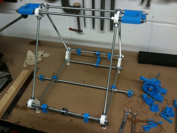
The next job is to adjust the bottom rods, top frame and roughly align the z-axis smooth rod holders which should be done early next week as I’m likely to be busy with other things over the weekend.
Posted on 11 October 2012